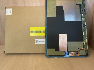
If you are worried about your Samsung Galaxy S24 Ultra camera not working as it should you may need to replace any or all of the rear cameras. The Samsung Galaxy’s rear cameras are not fixed in one assembly so you have the option to replace individual cameras. In this guide we will walk you through the process of accessing and replacing the rear cameras of the Samsung Galaxy S24 Ultra. Just follow the steps and instructions provided, and you will have your Samsung Galaxy S24 Ultra cameras working as before.
How To Start Samsung Galaxy S24 Ultra Rear Cameras Replacement

Well you should start your Samsung Galaxy S24 Ultra rear camera replacement by completing some pre-work actions. Such as you have to gather the necessary tools that will help you make the replacement process easier. Also you have to choose the right place for doing your Samsung Galaxy S24 Ultra replacement task. So here is the list of tools that will help you disassemble and reassemble the Samsung Galaxy S24 Ultra For rear camera replacement.
Necessary Tools And Replacement Parts
*Genuine Replacement Cameras for Samsung Galaxy S24 Ultra
*Opening picks
*Suction handle
*Heat gun, hair dryer, hot plate, hair straightener
*Flat tip spudger
*Pointed tip spudger
*Phillips #00 Screwdriver
*Tweezers
*Isopropyl Alcohol (90% or Greater)
*lint‑free cloth
Right Place for Samsung Galaxy S24 Ultra Rear Cameras Replacement
When replacing the rear cameras of your Samsung Galaxy S24 Ultra it is important to choose the right place to work. Here are some things to keep in mind.
*You need a Clean Surface. Find a clean flat surface to place your phone and tools. This will prevent any small parts from getting lost or dirty.
*Make sure the area has bright lighting so you can see all the small components clearly.
*Choose a quiet and distraction-free space to focus on the repair without interruptions.
*You also have to consider wearing gloves to protect your hands and safety glasses if you are working with sharp or fragile parts.
*Keep your tools organised and close by to make the process smoother.
Precautions
*After the above two very important considerations you have to take your phone in your hand and check its charging percentage. If it is more than 25% then you have to drain it to less than 25%. Because a charged lithium-ion battery is more likely to catch fire if it accidentally gets damaged.
*Also have to remove all the wired connections from your Samsung Galaxy S24 Ultra before the disassembling process.
Step #1. Switch of the Samsung Galaxy S24 Ultra For Rear Cameras Replacement

*First press the Side key on your phone (it’s on the right side).
*At the same time press and hold the lower part of the Volume key. Keep both buttons held down together.
*After a few seconds the “Power Off” menu will appear on your screen.
*Tap the “Power Off” option on the screen.
*Tap “Power Off” again to turn off your phone completely.
Step #2. Heat Application On the Back Plate

Well we have to apply some heat for melting the adhesive that is securing the backplate with the frame.
Though we can start disassembling without the heating process it might be a hard time. It is better to start with heating which makes separating the adhesive very easy.
*However you can use a heat gun, hair dryer, hair straightener or a hot plate on the back plate of the Samsung Galaxy S24 Ultra.
*Properly apply heat at the entire edges of the back plate.
*While heating please keep checking the phone’s surface with your hands. When it is too hot to touch, it is probably ready for disassembling.
Step #3. Place a Suction Handle

*After the heating process you need to place a suction handle at the right edge of the back plate.
*Please make sure the placing of the suction cup is in the centre.
*Pull the back plate with steady pressure holding the suction handle.
*The purpose is only to create a line gap between the back plate and the frame.
Step #4. Insert An Opening Pick to Separate the Adhesive


*When you see a line gap is created and your opening pick can easily go in then go ahead and insert an opening pick.
*Now remove the suction handle.
*Move the opening pick back and forth to separate the adhesive.
*Make sure all the right edge edge adhesive has separated and release the back plate from his side.
*Now take the opening pick toward the bottom right corner.
*Remember the Samsung Galaxy S24 Ultra has sharp edges. Slowly turn the opening pick to the bottom edge cutting the corner’s adhesive.
*Now slide the opening pick at the bottom edge to separate the adhesive.
*Well you can leave opening picks to prevent the back cover stick again. But if you are moving fast separating the adhesive then you go ahead without leaving the opening pick inserted at any edge.
*Now from the bottom left corner turn the pick toward the left edge of the Samsung Galaxy S24 Ultra.
*Slide the opening-pick upward until you reach the power button.
*Be careful while cutting the adhesive from the left edge side. Don’t damage the antenna cable.
*Leave the opening pick near the power button to prevent the adhesive from resealing.
*Insert a new opening pick from the right edge of the phone and move it upward.
*Turn the pick from the upper right corner and then cut the adhesive from the top edge of the phone.
*Here you may need to apply heat again. Using your heating equipment apply heat and separate the top edge of the back cover from the frame.
*Then slide the pick from the top left corner and move ahead toward the power button.
*Do not insert the pick more than 4 mm long to avoid damaging the sensor and cameras.
Step #5. Remove The Backplate of the Samsung Galaxy S24 Ultra

*Make sure you have cut all the adhesive and the back plate can be removed now.
*Grab the back plate with your hand and remove it from the frame.
*If the cover is still sticking to the frame, separate it with the help of an opening pick and release the cover.
*The back plate is free from any cable connection. So you can put it aside just after separating the adhesive.
Step #6. Disconnect Wireless Charging Coil

*Use a flat-tip spudger to carefully lift and disconnect the wireless charging coil’s connector from the motherboard.
*On the motherboard there is a small arrow next to each connector. This connector shows you the best spot to lift. Make sure to only pry in that area to avoid damaging small parts around it.
*Lift the connector slowly and gently to avoid putting too much pressure on the surrounding components.
Step #7. Remove Ten Screws From Wireless Charging Coil And Loudspeaker


*There are ten screws that have to be removed to remove the wireless charging coil.
*Four screws are on the wireless charging coil and six are securing the loudspeaker’s assembly.
*Use a Phillips screwdriver to unfasten the 3.5 mm long screws.
*Keep the screws in a safe place for using them while reassembling.
Step #8. Remove the Wireless Charging Coil and Loudspeaker


*The charging coil is also stuck with adhesive.
*Use a pointed tip spudger to pry up the charging coil tab from the right edge of the phone.
*Now you need an opening pick and insert it into the gap between the right edge of the loudspeaker and frame.
*Pry up the loudspeaker and lift it upward until it can come into your finger’s grip.
*You will have to unclip the loudspeaker from the frame.
*Now hold it with your fingers and remove it along with the changing coil.
Step #9. Disconnect the Battery From the Motherboard

*After removing the charging coil the battery press connection will be visible.
*You will need a pointed tip spudger for prying it up and disconnecting it from the board.
*Battery disconnection will make your replacement more safe and secure.
Step #10. Remove Earpiece Speaker


*Now move towards removing the earpiece speaker.
*First of all disconnect its connection from the board.
*Pry up with a pointed tip spudger and disconnect it.
*Then unfasten its screws. It is secured with five 3.5 mm long screws.
*Use a Phillips screwdriver to open these screws and keep them all safely aside.
*Insert a pointed-tip spudger into the bottom of the earpiece speaker.
*Unclip it from the frame and remove it.
Step #11. Disconnecting And Removing Interconnection Cables


*It’s time to disconnect both the interconnect cables from the motherboard.
*Pry up both the interconnect cables from the upper side using a pointed-tip spudger and disconnect the first cable.
*Now pry up both the interconnect cables with the pointed end spudger and disconnect the wires from the daughterboard.
*And then remove them from the phone.
Step #12. Disconnect the Screen Cable


*Now move to disconnect the screen cable.
*Take a pointed-tip spudger and pry it up the display press cable to disconnect it from the motherboard.
*Now disconnect the display press cable from the daughterboard.
*Then remove the display cable from the phone.
Step #13. Disconnect the Lower Antenna

*You will see that the entire battery is evident. No cables are crossing it but only the lower antenna is going from the left edge to the top edge of the battery.
*So you have to remove it too.
*Disconnect the lower antenna from the motherboard.
Step #14. Disconnect the Stylus Port From the Motherboard

*Pry up the stylus port press cable using a pointed tip spudger and disconnect it from the motherboard.
Step #15. Disconnect the Upper Antenna From the Motherboard

*The Upper antenna is just located at the top of the stylus port.
*Pry it up with the spudger and disconnect its press cable from the motherboard.
Step #16. Disconnect the Fingerprint Scanner

*Use a spudger to pry up the fingerprint antenna’s press cable connector and disconnect it from the motherboard.
Step #17. Disconnect the Front Camera

*Now move toward the front camera that also needs to be disconnected.
*Use the same spudger to pry up the front camera’s press connector cable.
*Disconnect it from the motherboard.
*Now make sure all the cables are disconnected from the motherboard and it is ready to be opened.
Step #18. Remove the Motherboard Screws

Two screws still secure the motherboard to the frame.
*Use a Phillips screwdriver to take out the two screws that hold the motherboard.
*First remove the 4.0 mm screw located next to the top camera. Keep it in a safe place for later use.
*Then remove the 3.5 mm long screw located next to the bottom camera. Store it safely too.
*Both screws are important for holding the motherboard so remember where they go when you need to put everything back together.
Step #19. Remove the Motherboard From the Frame

*Gently use your finger or a spudger to lift the top part of the motherboard from the phone.
*Once it’s loose carefully remove the entire motherboard.
Precautions
*Make sure to watch out for any loose cables or connectors so they don’t get snagged or damaged while you are taking the motherboard out. Handle the board with care to avoid bending or breaking any components.
Step #20. Disconnect the Rear Cameras


*The rear camera’s press connectors are connected from the flip side of the Motherboard.
*So please flip the motherboard and look for the camera’s connections.
*Using a spudger pry up the primary telephoto camera press connector and disconnect it from the Motherboard.
*Use a spudger to gently pry up and disconnect the press connector for the secondary telephoto camera. Be careful not to damage any nearby components while doing this.
*Next use the spudger to carefully lift and disconnect the press connector for the main camera. Take your time to avoid bending or breaking any pins.
*Finally use the spudger to lift and disconnect the ultrawide camera’s press connector. Make sure to apply gentle pressure to avoid damaging the connector or surrounding parts.
*At this stage the camera’s assembly housing is free from the motherboard.
Step #21. Unfasten the Rear Camera Screw and Remove the Cameras

*Use a Phillips screwdriver to unscrew the 3.5 mm‑long screw that secures the cameras to the camera assembly housing.
*Once the screw is removed gently flip the cameras over so that the lenses are facing upwards.
*Carefully lift and remove the primary telephoto camera from the housing. Set it aside.
*Next you will lift and remove the secondary telephoto camera. This camera may have a small amount of adhesive around its alignment pin. So be gentle when removing it.
*Now take a spudger and slide the flat end between the bottom of the ultrawide camera and the metal housing. Be sure to place the spudger between the cable and the metal housing not between the cable and the camera.
*Carefully pry the ultrawide camera free from the adhesive holding it in place.
*Once the adhesive is loosened remove the ultrawide camera from the housing.
*At this point all rear cameras have been removed and are ready for replacement.
Step #22. Replace The Rear Cameras Of The Samsung Galaxy S24 Ultra

*To replace the rear cameras of the Samsung Galaxy S24 Ultra you can begin by placing the ultrawide camera into the camera assembly housing. Make sure it aligns appropriately with the pin and fits securely into place. Gently press it down so the adhesive holds it firmly.
*Next you need to install the secondary telephoto camera. Please make sure it slides into its slot and sits appropriately within the housing. Press it lightly to attach it securely.
*Now place the primary telephoto camera in the correct position within the housing. Then press it down gently to ensure it is seated properly.
*Once all cameras are installed use a Phillips screwdriver to reinstall the 3.5 mm-long screw that secures the cameras in place.
*Finally flip the cameras so their lenses face down. It is ready for connection to the press connectors.
*Here we are guiding all the cameras. But you have options for replacing any of your desired cameras from the Samsung Galaxy S24 ultra.
Step #23. Connect All the Cameras To the Camera Housing


*Start by lining up the ultrawide camera connector with its socket on the motherboard. Gently press it down until it clicks in place.
*Next you will take the main camera connector and carefully line it up with its socket. Press down on one side and then the other to make sure it is connected.
*Do the same for the secondary telephoto camera. Line up its connector and gently press it down into its socket.
*Check each connection to make sure they are secure and that no cables are stuck or out of place.
Step #24. Reinsert the Motherboard

*After connecting the cameras to the motherboard it is ready to reassemble.
*Make sure that all press connectors are positioned above the motherboard as you reinsert it.
*Carefully place the motherboard back into the phone. Make sure all connectors and cables are correctly aligned with their respective slots.
*Use your fingers or a spudger to lift the top of the motherboard slightly if needed to make sure it sits properly in the phone’s frame.
*Use a Phillips screwdriver to insert and tighten the screws that hold the motherboard in place. One screw goes near the top camera and the other near the bottom camera. Be careful not to overtighten.
Step #25. Connect All the Cables to The Motherboard


*Now the motherboard is ready for all the connections.
*Connect the front camera press connector to the motherboard.
*Then connect the fingerprint scanner to the motherboard.
*Now press down the upper antenna’s press cable connection.
*Press the stylus port cable into its socket.
*And then align the lower antenna with its socket into the motherboard.
Step #26. Reassemble the Display and Interconnected Cables

*It’s time to place the display and interconnected cables in their respective places.
*Now we will connect them to the boards.
*Firstly connect the display cable to the daughterboard and then insert the display press connector to the motherboard.
*Make sure you feel the snug fit into the socket.
*Now press the interconnector cable to the daughterboard and reconnect the interconnections to the motherboard.
*Make sure to connect both the interconnect cables.
Step #27. Reassemble the Earpiece Speaker


*Place the top edge of the earpiece speaker into the frame first. Make sure it is correctly aligned before pressing it down to clip it back into place.
*Use a Phillips screwdriver to insert and tighten the five 3.5 mm-long screws that hold the earpiece speaker in place.
*Use a spudger to gently press down and reconnect the earpiece speaker press connector to the motherboard. Make sure it is firmly and properly connected.
Step #28. Reconnect the Battery

*Now we will reconnect the battery to the motherboard.
*Make sure the connection is snug fit.
Step #29. Reinstall The Wireless Charging Coil

*Position the wireless charging coil back into its slot on the motherboard covering the battery.
*Use the Phillips screwdriver to insert and tighten the four screws that secure the charging coil in place.
*Position the loudspeaker so that it fits properly into its slot. Press around the edges of the loudspeaker to ensure it clips securely to the frame.
*Use the Phillips screwdriver to insert and tighten the six screws that hold the loudspeaker in place.
*Carefully align the press connectors over their sockets. Press down gently with your fingertip. It will be helpful if you start on one side and then the other until the connectors click into place. Avoid forcing them. If needed, adjust and try again.
Step #30. Reassembling the Back Plate


*Power on your phone to test all functions. Make sure everything works correctly before sealing it up. Turn off the phone completely before continuing with the next steps.
*Use tweezers or your fingers to remove any old adhesive chunks from the frame. If needed you can apply gentle heat to help loosen stubborn adhesive.
*Place the adhesive strip with the clear liner facing down over the frame. Use the rear camera cutout as a guide to ensure proper alignment.
*If your custom-cut adhesive strip matches the back plate’s alignment then do it for the back plate.
*Peel off the clear liner from the adhesive strip to expose the sticky side. Be careful to align it correctly because once it sticks you can’t reposition it.
*Carefully press the sticky side of the adhesive strip around the edges of the frame. Use the screw holes to help with alignment.
*Peel off the coloured liner from the adhesive strip to reveal the adhesive on the other side.
*Position the back cover over the frame. Please make sure it aligns with the adhesive.
*Firmly press the perimeter of the back cover to bond it to the adhesive strip.
*Apply consistent pressure on the back cover with a flat, heavy object like a book to make sure a good seal.
*If there is a noticeable gap try to squeeze it gently with your fingers without forcing it.
Congratulations!
Great job! We have successfully completed the Samsung Galaxy S24 Ultra Rear Cameras Replacement. We hope that everything is going perfectly on your side too. This step-by-step guide has mentioned all the steps, precautions and tips for making your Samsung Galaxy S24 ultra rear camera replacement smoother.
If you have anything to say you can write to us in the comment section or you can Email us. Best of luck!
Admin